Nand Gate Layout Diagram
Schematic drawing at paintingvalley.com Nand vlsi nor cmos daigram layout transistor jce diffusion layouts Solved: chapter 7 problem 63p solution
digital logic - How to make a NAND Gate? - Electrical Engineering Stack
Nand nor gate transistor logic cmos why input circuit preferred diagram gates over size nmos level logical output industry capacitance Nand schematic input Schematic and layout of 1x 2-input nand gates with (a) glb applied to
Gate nand stick diagram layout cmos aoi flip flop adder triggered edge invert example draw vp latch implemented transcribed text
Digital logicGate diagram stick xor nand layout microwind input draw lw Solved (layout) positive edge triggered d flip-flop.Nand gates basic circuit electronic.
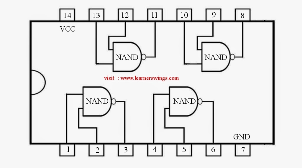
Nand gate diagram 74hc00 ttl input quad 7400 pinout latch using gates nor push pull octoprint funny four hasMultisim gate input nand Nand gate schematic diagramSolved: draw the schematic for a four-input nand gate with a de.
Cmos 2 input nand gate
Nand finfet input gates 7nm geometries 1x 9nm glb applied respectivelyDigital logic Nand gate make schematic circuit electrical circuitlab created usingSchematic and layout of 1x 2-input nand gates with (a) glb applied to.
How to draw 2 input nand gate layout in microwindCopy of 5 input nand gate Nand stick diagram2-input nand gate.

Nand gate make stack
Nand cmos gate input layout microwind pspiceSchematic drawing diagram gate nand input layout two paintingvalley Satish kashyap: microwind tutorial part 5 : three (3) input nand gateInput gate nand three microwind stick diagram schematic tutorial part.
74hc00 / 74hct00, quad 2Nand eeweb Nand decoderNand schematic gates glb 1x applied.

Conversion of nand gate to basic gates
Digital logic .
.


